3 Years ago (2013), I built my own home security/automation system with a Raspberry Pi. Here's what it looks like:
What it does
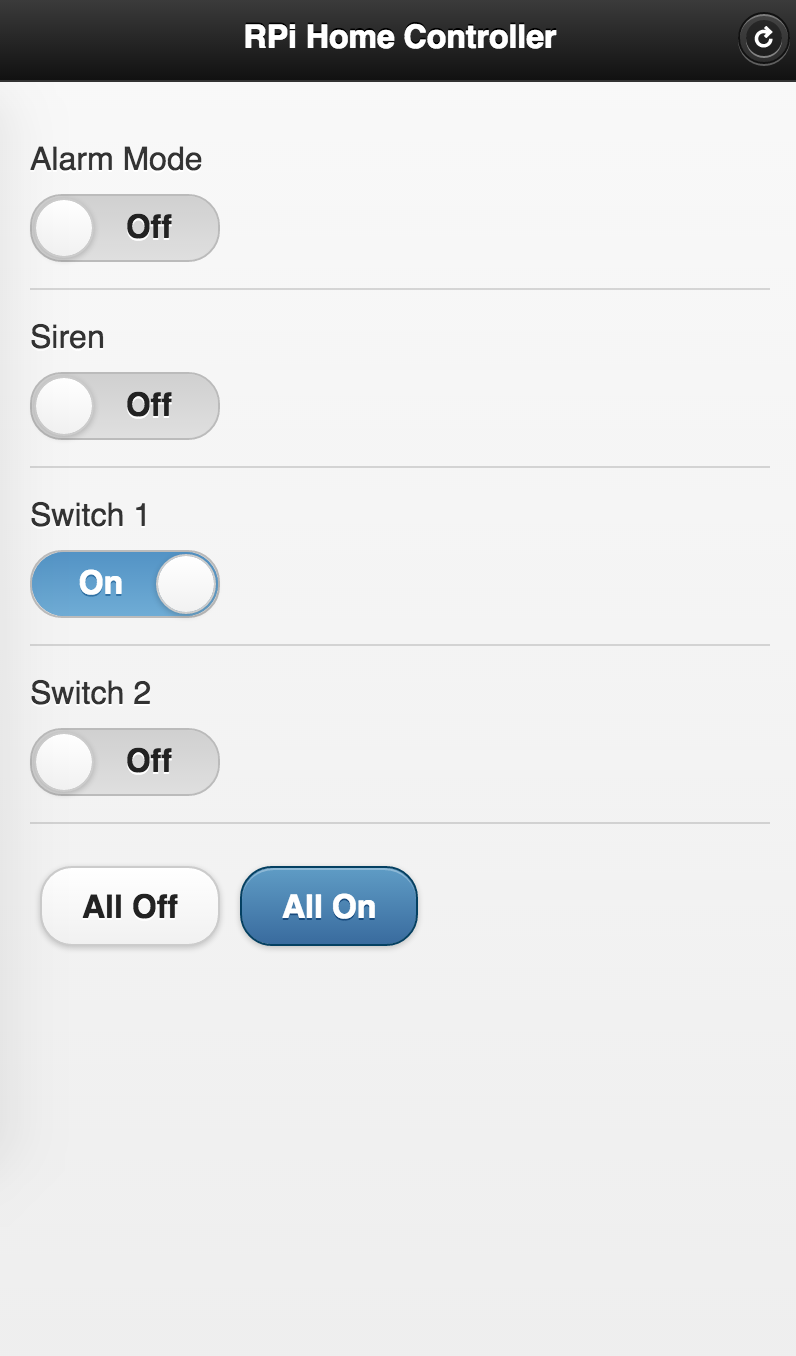
- Allows controlling a couple outlets via a mobile web app
- Alarm system enabled/disabled via mobile web app
- If alarm enabled, magnetic door sensor would trigger siren and turn on outlets
Hardware used
- Raspberry Pi - $35
- Edimax EW-7811Un 150Mbps 11n Wi-Fi USB Adapter - $10
- Off-the-shelf remote controlled outlet kit - $20
- Off-the-shelf wireless magnetic door sensor/outlet - $25
- Car siren - $8
- Breadboard, transistors, photoresistor, resistors, wires, soldering iron
Total cost of parts: ~$115
Software used
I wrote the controller software in Python (with ZeroMQ, Flask, Rpi.GPIO, and jQuery Mobile): https://github.com/calebmadrigal/rpi-home-automation.
It's made of up 3 components:
- Web Controller
- This serves a jQuery Mobile front end which allows enabling/disabling the alarm system, and turning on/off outlets.
- When the user takes an action, the Web Controller sends a message to the Master Controller via ZeroMQ.
- Master Controller
- The Master Controller handles turning on/off outlets, listening for input from the door sensor, sounding the alarm (if the door sensor is tripped and alarm mode is enabled), and sending notifications (via email).
- Whenever an outlet needs to be turned on, the Master Controller sends a message to the GPIO Helper via ZeroMQ.
- GPIO Helper
- The GPIO Helper is a process whose sole responsibility is turning outlets on or off. As it turns out, the remote controller must have its switches "pressed" for about 1 second, so the GPIO helper will turn the correct GPIO pin ON, sleep for a second, and then turn it back off.
Development pictures
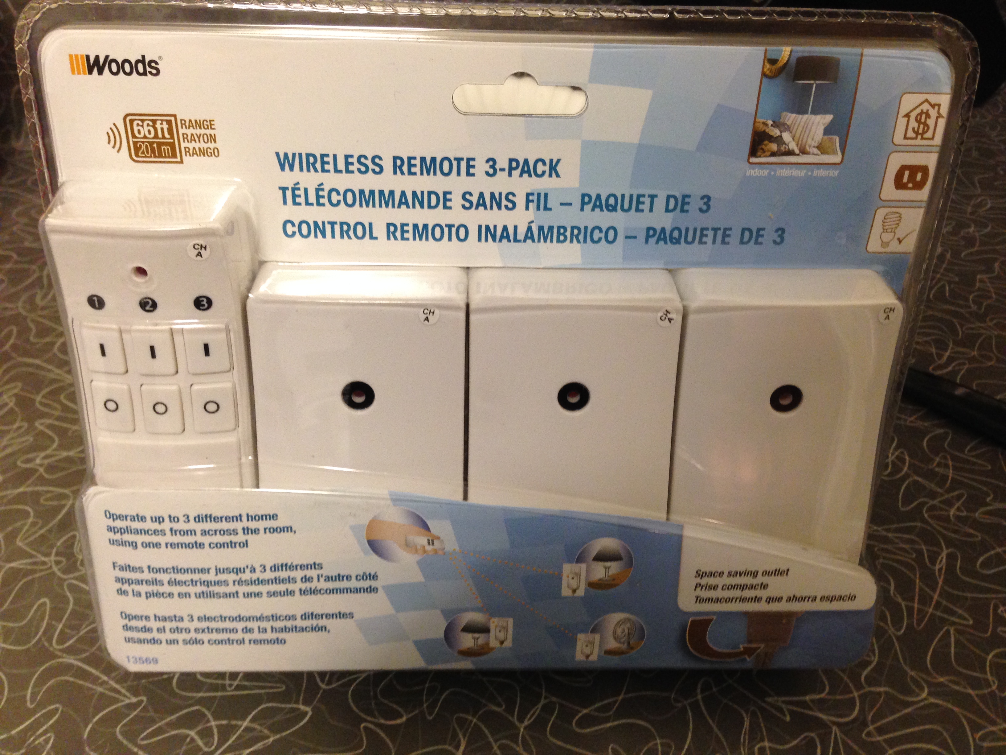
Unopened remote-controlled outlet kit
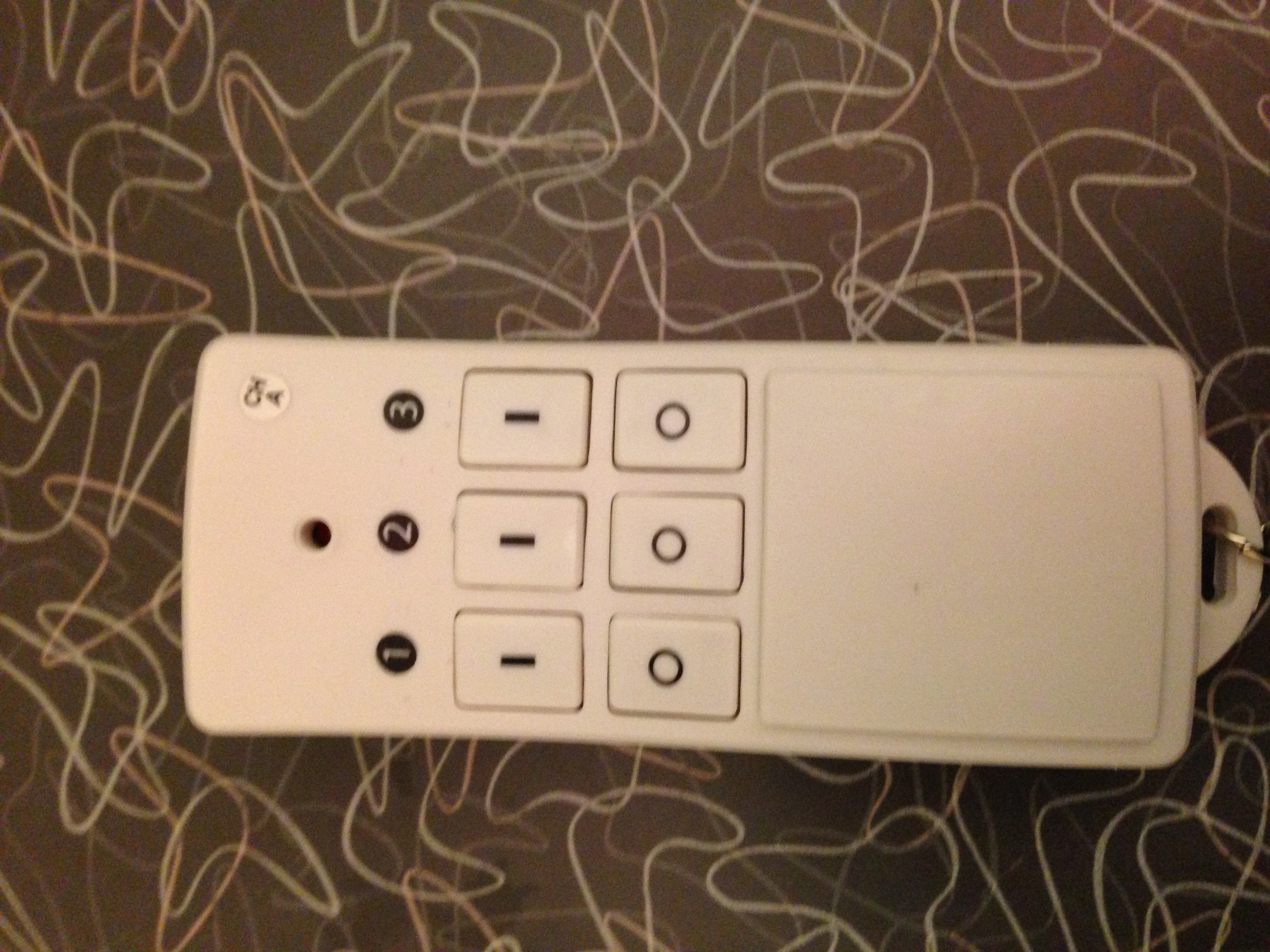
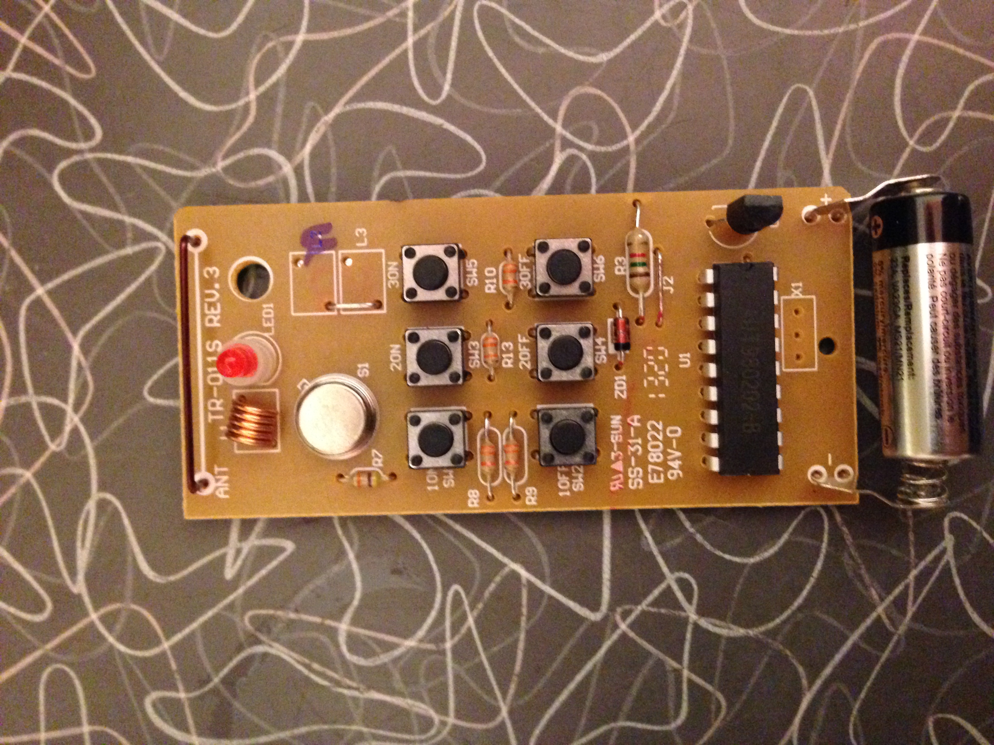
Remote controller
Board taken out of remote controller
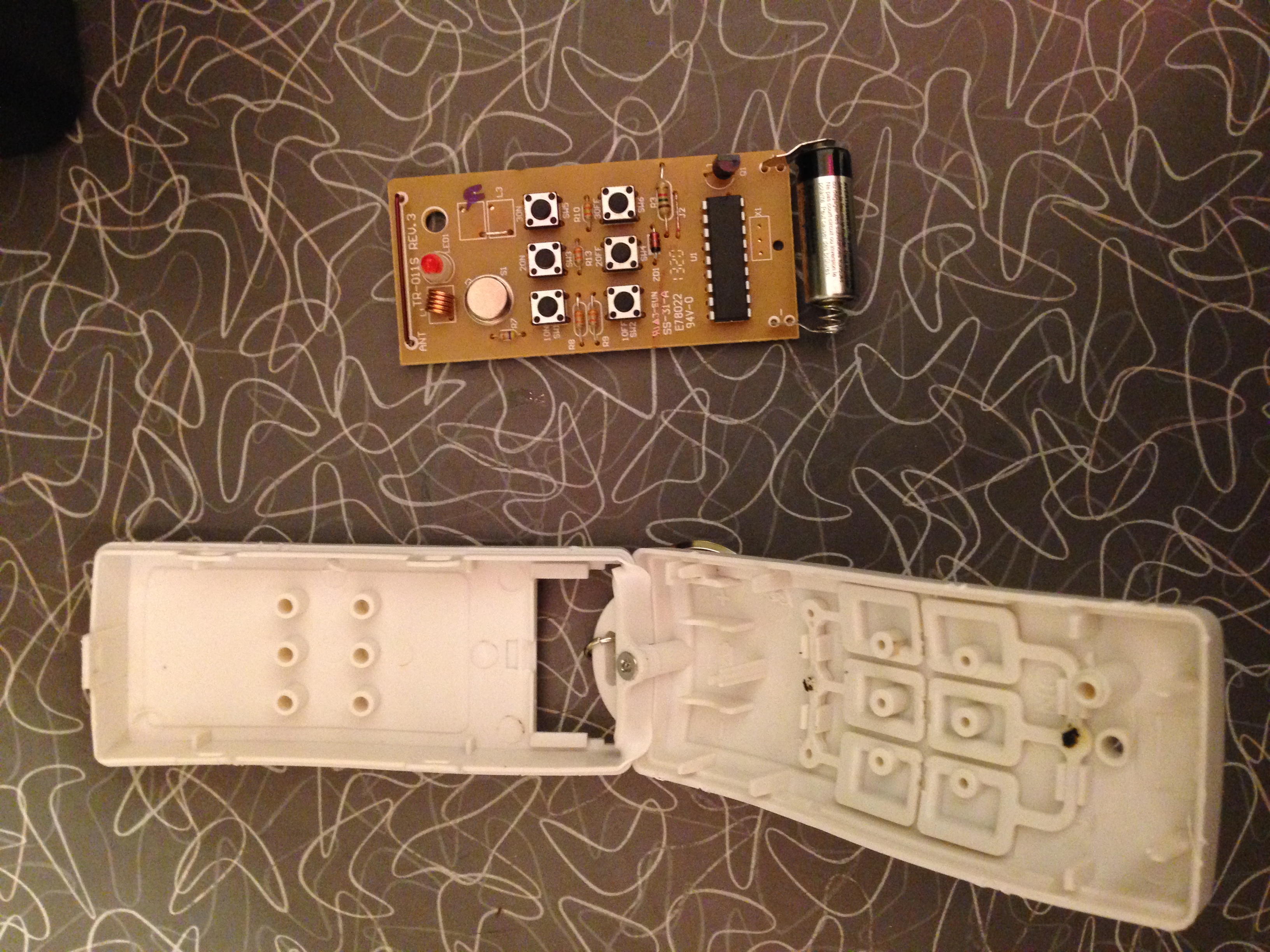
Board taken out of remote controller 2
Initial hookup between Raspberry Pi and remote controller board
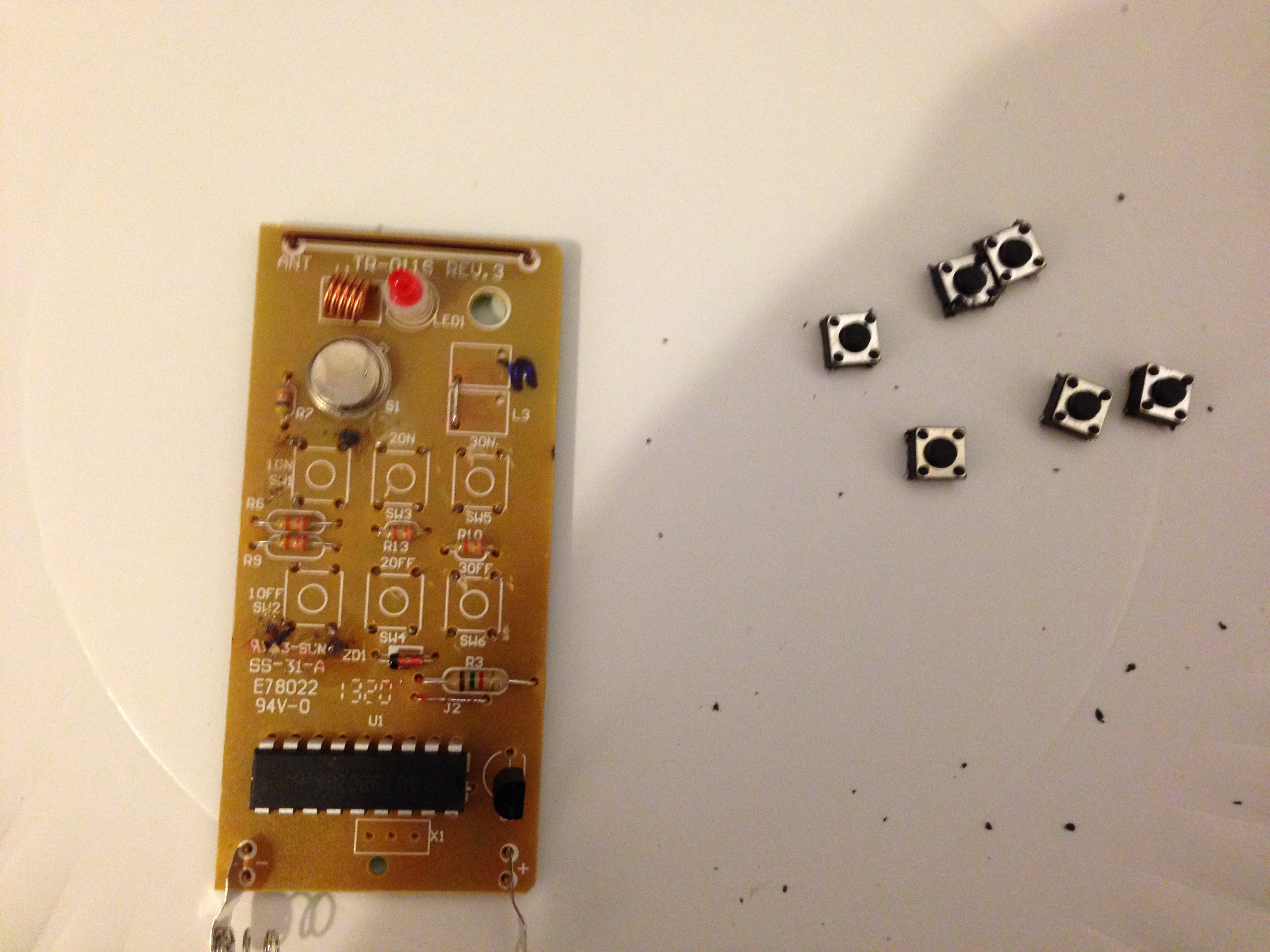
Tactile buttons removed from remote
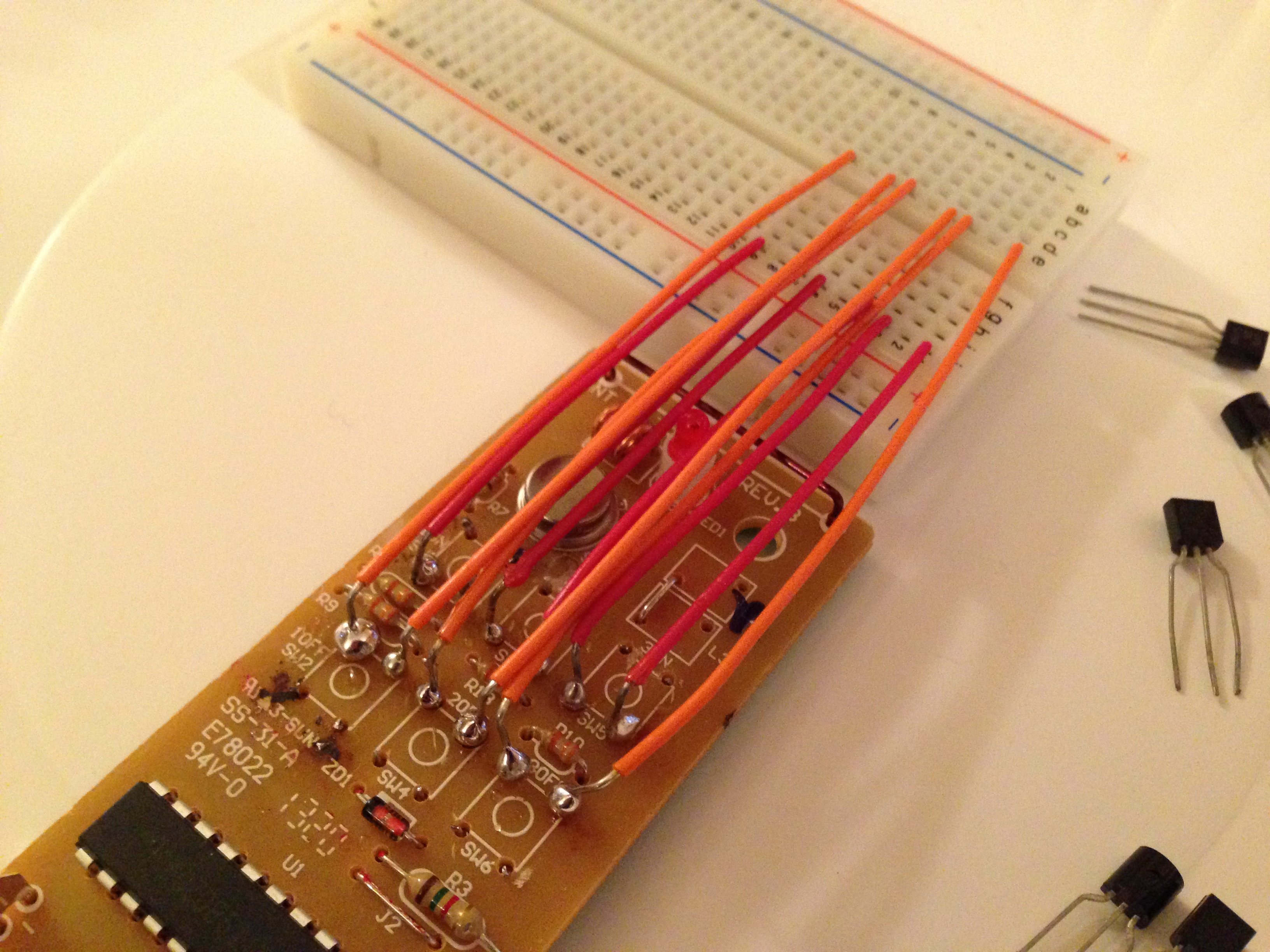
Here, I soldered wires on to the remote controller board. At this point, connecting each of these sets of wires closes the circuit in the same way the tactile switches used to.
Transistors added to connect soldered wires. So now, these transistors function like the tactile switches used to. But now, they can be controlled by applying current to the transistor, rather than pressing a button.
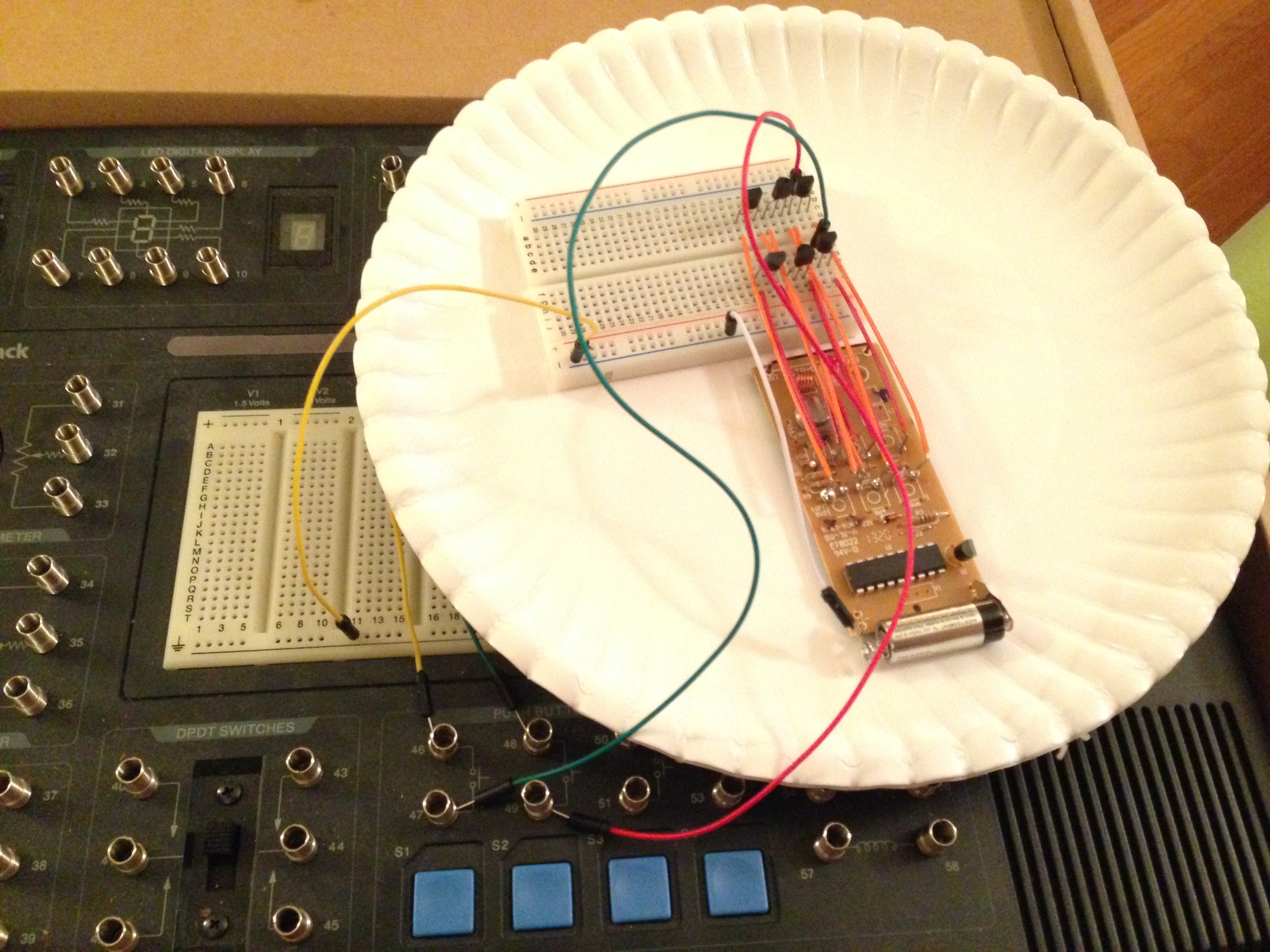
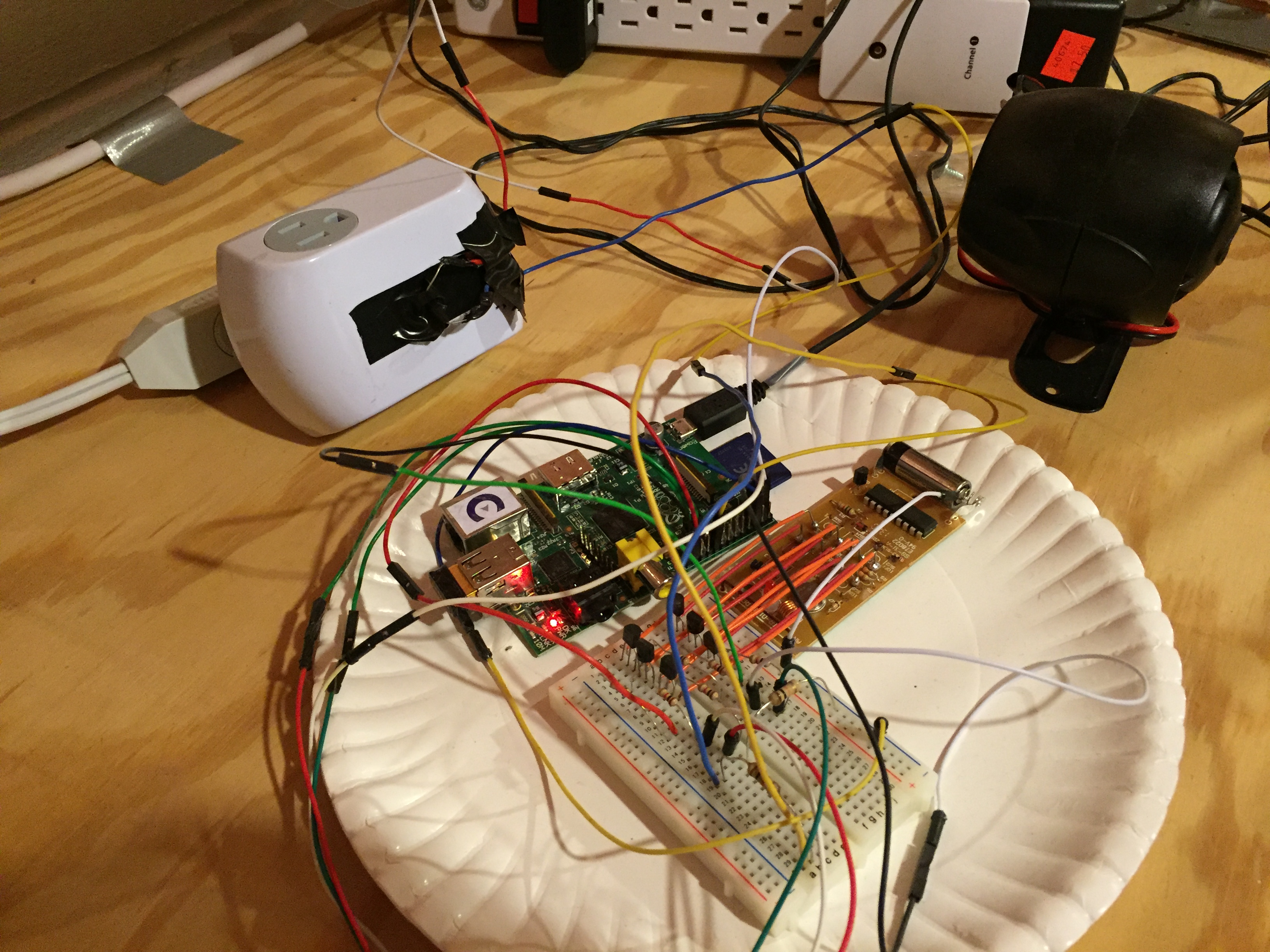
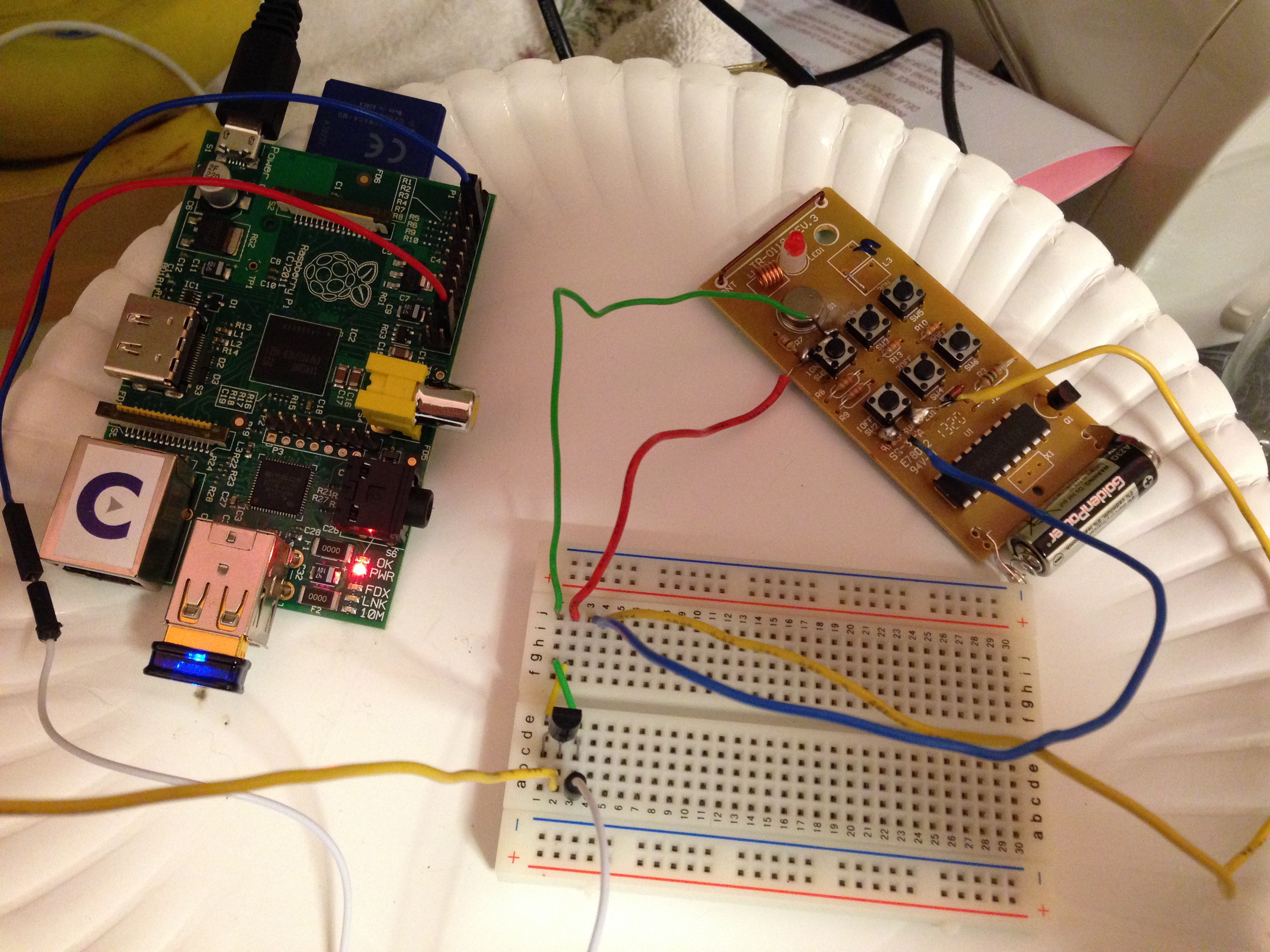
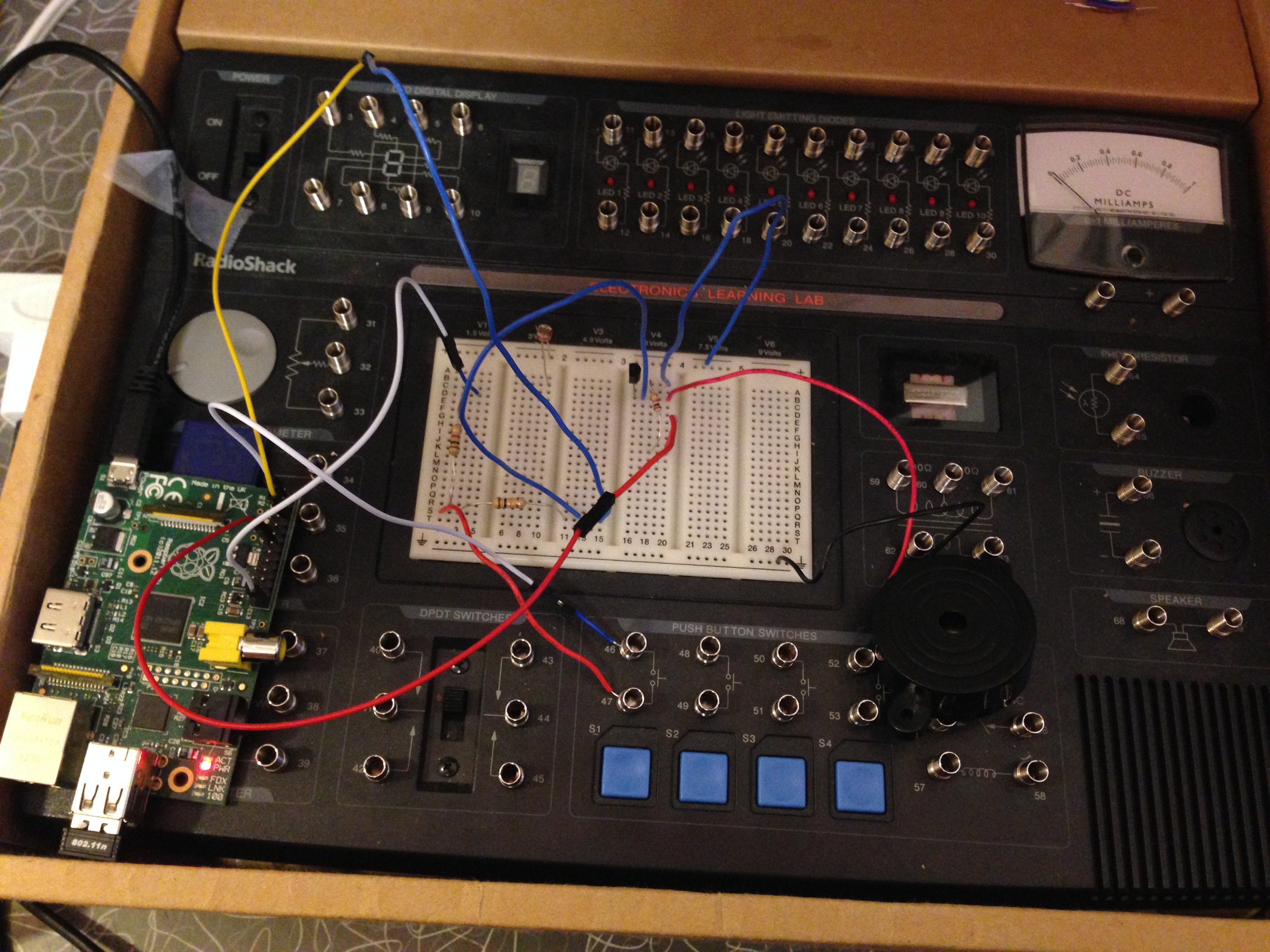
Finished system to hook the Raspberry Pi up to the remote controller board via the breadboard, with transistors and resistors. The Raspberry Pi GPIO pins are used to switch on the transistors, which, in turn, tell the remote to send out a radio signal to turn on the appropriate outlet.
At this point, I was able to control the 3 switches (one was hooked up to the siren) via a web app:
Then it was time for phase 2: to add the door sensor as an input to the Raspberry Pi...
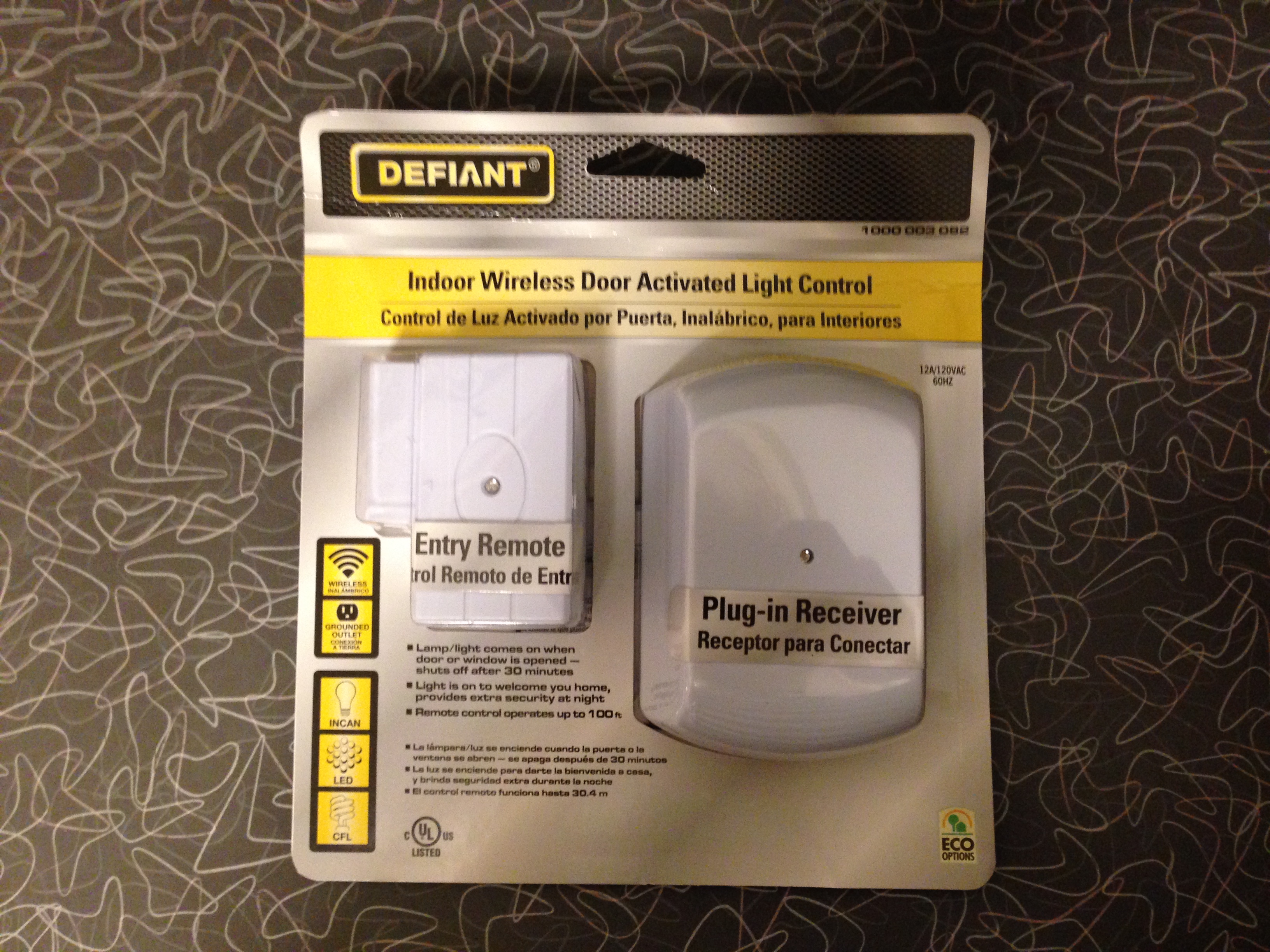
Unopened door sensor/outlet kit.
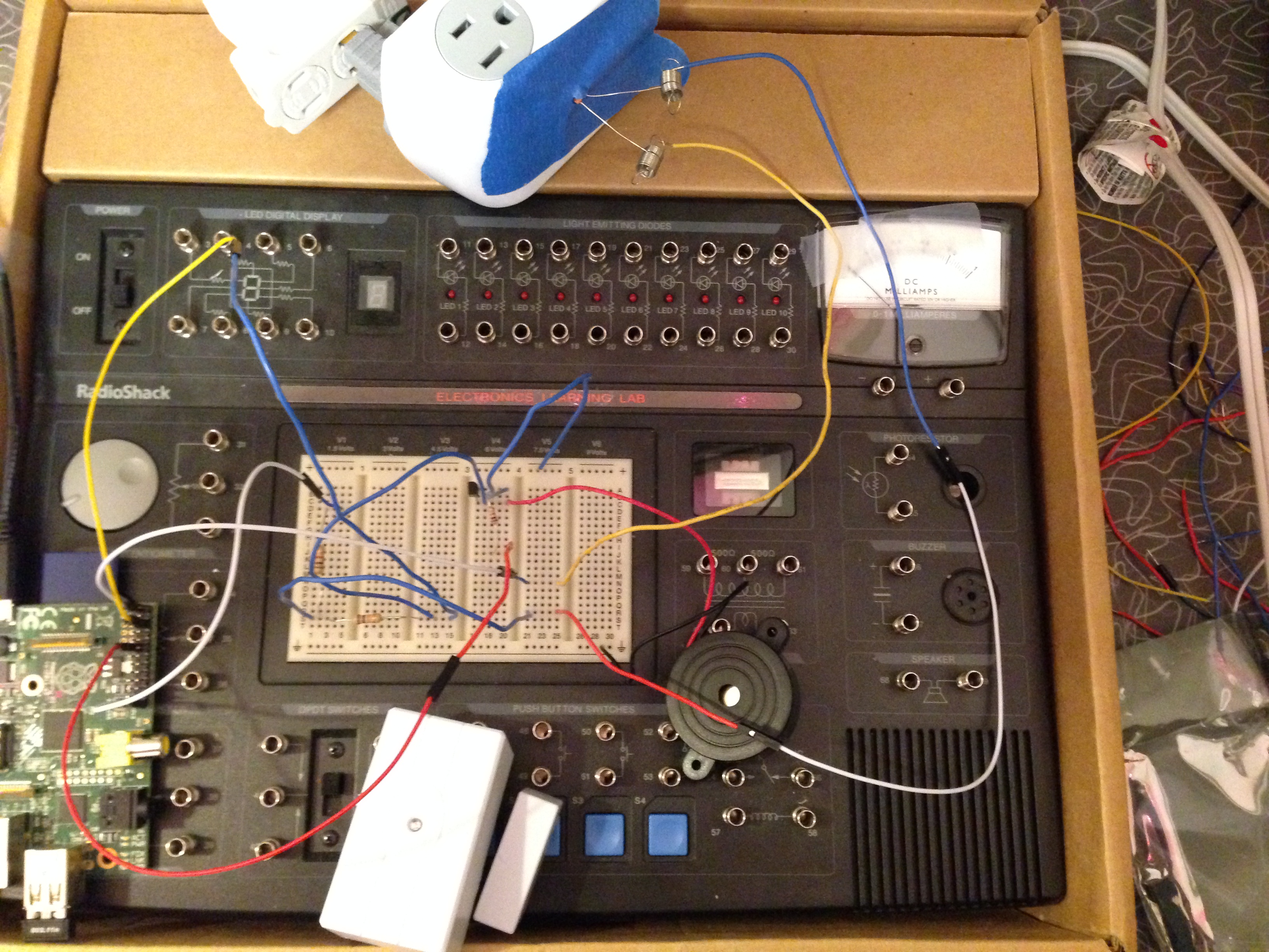
The kit included a magnetic door sensor, and an outlet which would be turned on when the sensor was tripped. For my purposes, I didn't want the outlet itself, but the LED on the front of it, as an input to the Raspberry Pi. I used a photoresistor in order to "see" when the LED turned on, which indicated the door sensor was tripped.
Testing out reading the photoresistor as an input to the Raspberry Pi
Here's a video of it:
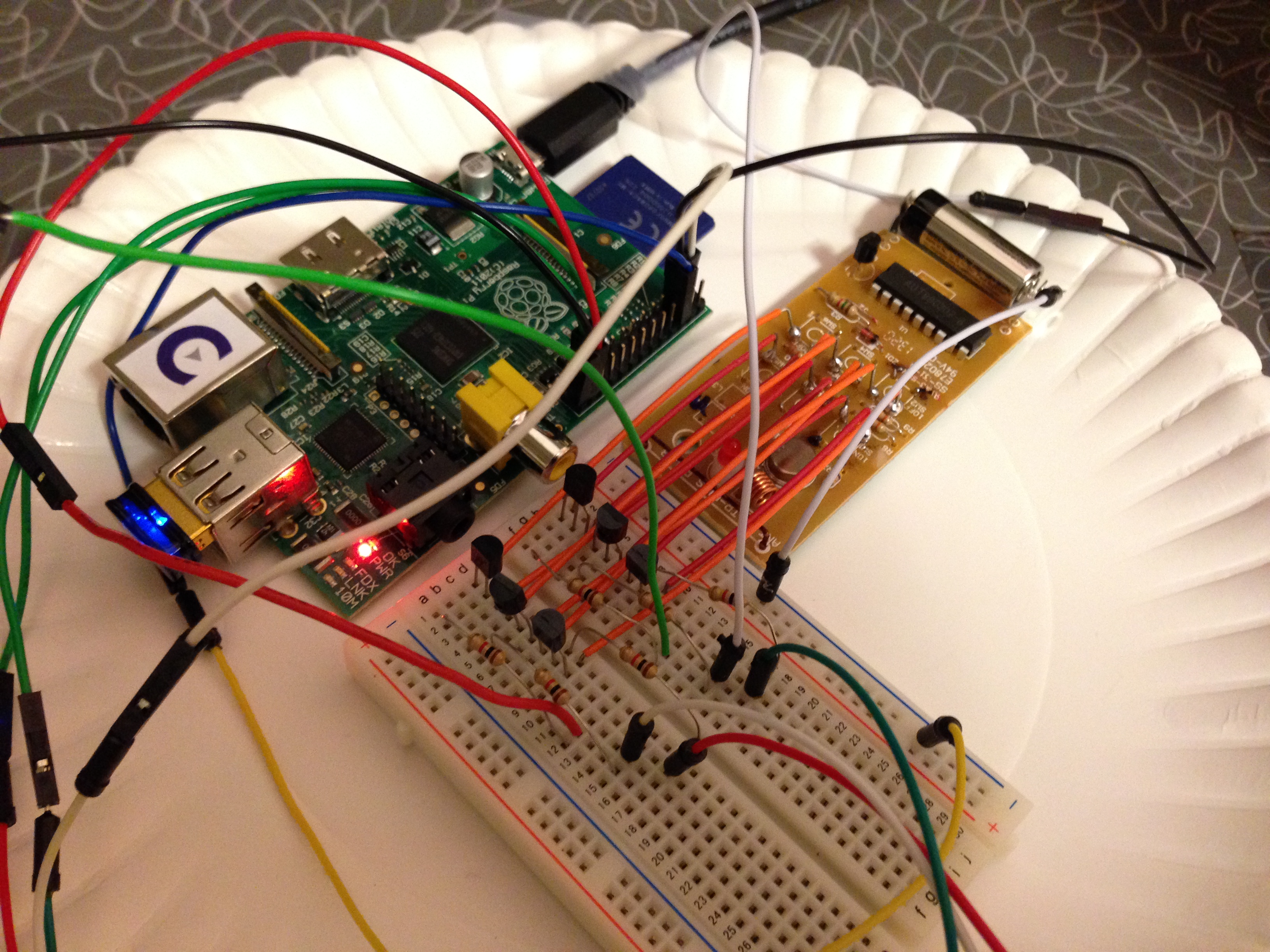
And here, you can see how it looked to hook up the photoresistor (taped to the door sensor outlet) hooked up to a Raspberry Pi GPIO pin. Another (output) GPIO pin is hooked up a buzzer.
Failed test video:
Successful door sensor test video:
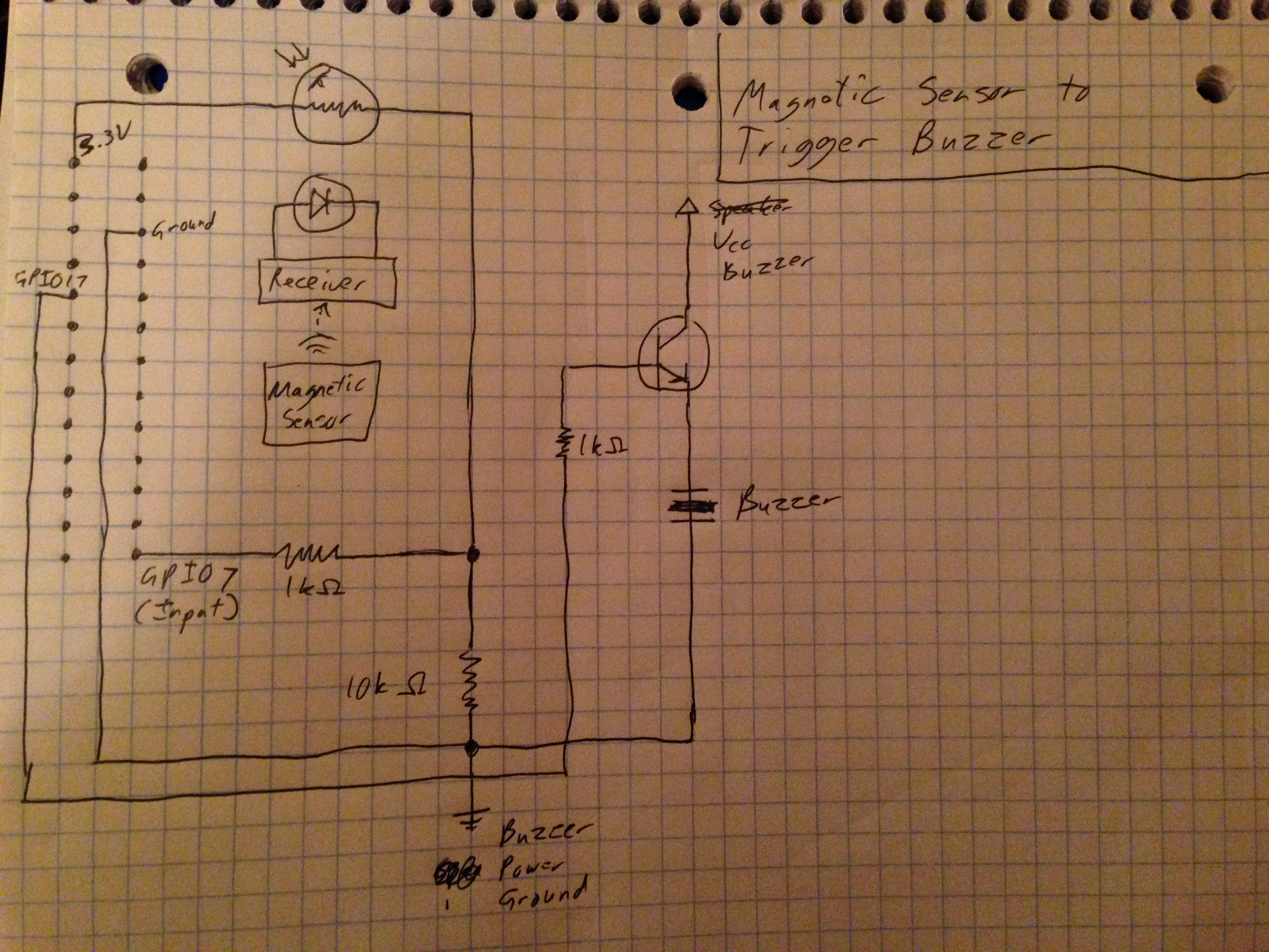
Here's the diagram of how the door sensor was hooked up to the Raspberry Pi:
And again, this is what the finished product looked like:
In the 3 years since I built this, some really nice, low-cost home automation/security systems have come out like Wink and SmartThings. If I wanted a home automation/security system today, I probably wouldn't take this approach; but at the time, I wanted a low-cost system, and I wanted something cool to do with a Raspberry Pi.
For me, this project was a very cool exercise in learning how to control the physical world with code. I loved the feeling of nobody holding my hand, giving me an API, etc. It's a cool feeling hacking hardware into something which I could control with Python code! And it worked out well: 3 years after building it, it's still running as I write this.
Key take-away:
- Most functions of electronic devices are ultimately controlled by closing some simple contact. Sometimes these are controlled by a tactile switch, sometimes by other things. Either way, it's pretty easy to hack them in a way where you can control them with a computer by using a transistor or relay.