Recently, I was curious if I could generate a digital radio signal from scratch just using math, and use that signal to control this radio-controlled outlet that I have.
Here's the Github source: https://github.com/calebmadrigal/radio-hacking-scripts/blob/master/radio_signal_generation.ipynb
Generating radio signals
I want to be able to generate modulated digital signals such as this one...
original radio signal
This is a binary signal coded with On-off keying (also known as Amplitude-shift keying).
I'm taking the long pulses to mean "1" and the short pulses to mean "0", so this signal is transmitting the digital code, "0110100010000000".
# Imports and boilerplate to make graphs look better
%matplotlib inline
import matplotlib.pyplot as plt
import numpy as np
import scipy
import wave
from IPython.display import Audio

def setup_graph(title='', x_label='', y_label='', fig_size=None):
    fig = plt.figure()
    if fig_size != None:
        fig.set_size_inches(fig_size[0], fig_size[1])
    ax = fig.add_subplot(111)
    ax.set_title(title)
    ax.set_xlabel(x_label)
    ax.set_ylabel(y_label)
Basic wave functions
SAMPLE_BITSIZE = 16
MAX_AMP_16BIT = int(2**SAMPLE_BITSIZE/2 - 1)

def generate_wave(freq, len_in_sec=1, samp_rate=44100, amplitude=MAX_AMP_16BIT):
    t = np.linspace(0, len_in_sec, samp_rate * len_in_sec)
    sig = amplitude * np.sin(freq * 2 * np.pi * t)
    return sig

def write_wav_file(file_path, wav_data, sample_rate=44100, num_channels=1):
    f = wave.open(file_path, 'wb')
    f.setparams((num_channels, 2, sample_rate, len(wav_data), "NONE", "Uncompressed"))
    f.writeframes(np.array(wav_data, dtype=np.int16))
    f.close()

def write_pcm_file(signal_data, file_path, dtype='complex64'):
    np.array(signal_data).astype(dtype).tofile(file_path)
Amplitude modulation
First, we need to figure out how to modulate the amplitude of the carrier wave to "high amplitude" and "low amplitude" to correspond with the binary"s and 0s.
samp_rate = 1000
len_in_sec = 1
carrier_freq = 20

low_amp = 0.1
high_amp = 1

t = np.linspace(0, 1, samp_rate * len_in_sec)
carrier = 1*np.sin(carrier_freq * 2 * np.pi * t)

# Modulate with the binary signal: ['0', '1']
amp_mult = np.array([low_amp]*500 + [high_amp]*500)
sig = amp_mult * carrier

setup_graph(title='sig', x_label='time', y_label='freq', fig_size=(12,6))
plt.plot(t, sig)

So looking at the above example, let's see how we calculate the size of the multiplier array...
- The carrier frequency is 20Hz.
- The baud, in this case, is 2 bits per second, which is why we need 1 second to contain the 2 bits.
- The size of the multiplier wave to modulate the carrier wave is 1000 in size because it must match the number of samples there are (which in this case, 1 second x 1000 samples per second = 1000).
- Note the width of each bit (in terms of samples) is samples_per_second / bits_per_second = 1000 / 2 = 500
Write function to modulate amplitude according to binary data
To modulate the carrier wave signal, we will simply: * Generate the carrier wave * Generate a "modulation array" - an array with the LOW or HIGH amplitudes for each data point in the carrier wave array * Multiply the "carrier wave array" with the "modulation array", to result in the "modulated signal"
SAMPLE_BITSIZE = 16
MAX_AMP_16BIT = int(2**SAMPLE_BITSIZE/2 - 1)

DEFAULT_RATIOS = {
    '_': 1,
    '0': 1,
    '1': 3
}

DEFAULT_AMP_MAP = {
    '0': MAX_AMP_16BIT * .02,
    '1': MAX_AMP_16BIT
}

def get_modulation_array(binary_data, sample_rate, baud, sig_ratios, amp_map, dtype=np.int16):
    data_points_in_bit = int(sample_rate * 1/baud)
    modulation_array = np.array([], dtype=dtype)

    for bit in binary_data:
        bit_amplitude = amp_map[bit]
        modulated_bit = np.full(data_points_in_bit, bit_amplitude, dtype=np.int16)
        modulation_array = np.append(modulation_array, modulated_bit)
    return modulation_array

def generate_on_off_key_signal(binary_data, carrier_wave_freq, sample_rate,
                               baud, sig_ratios=DEFAULT_RATIOS, amp_map=DEFAULT_AMP_MAP, dtype=np.int16):
    signal_len_secs = len(binary_data) * (1/baud)
    t = np.linspace(0, signal_len_secs, sample_rate * signal_len_secs)

    carrier_wave = 1 * np.sin(carrier_wave_freq * 2 * np.pi * t)
    modulation_array = get_modulation_array(binary_data, sample_rate, baud, sig_ratios, amp_map, dtype)
    return t, carrier_wave * modulation_array


binary_data = '0110100010000000'
carrier_wave_freq = 20 #315e6
sample_rate = 100
baud = 1

t, sig = generate_on_off_key_signal(binary_data, carrier_wave_freq, sample_rate, baud)
setup_graph(title='sig', x_label='time', y_label='freq', fig_size=(12,6))
plt.plot(t, sig)

Sweet! So it looks like it roughly worked. But there is a problem: we have no breaks between bits (so a group of 1's looks like a single pulse). Let's fix that...
Add the zero pulse and bit spacing
There are 2 problems with the above approach: * Zeros should actually have a short pulse rather than LOW amplitude * Bits should be spaced apart from each other
To accomplish this, we'll just rewrite the get_modulation_array() function so that each "modulated bit" will contain both the "1" or "0" pulse AND a "space" (which will simply be the LOW value).
Also, for simplicity/efficienty, we can just calculate the "1" and "0" modulation arrays once and reuse them.
I'm also going to turn up the sample rate a bit to get a more accurate signal.
DEFAULT_AMP_MAP = {
    'LOW': MAX_AMP_16BIT * .02,
    'HIGH': MAX_AMP_16BIT
}

def get_modulation_array(binary_data, sample_rate, baud, sig_ratios, amp_map, dtype=np.int16):
    data_points_in_bit = int(sample_rate * 1/baud)
    modulation_array = np.array([], dtype=dtype)

    # To describe this general algorithms, I'll use the specific concrete pulse ratios:
    #    '_': 1,
    #    '0': 1,
    #    '1': 3
    # Meaning that a "1" should be 3x longer than a "0" or a "space" pulse. Now since we need a space
    # between "1"s (as well as "0"), we can calculate that the pulse for a "1" should be 3/4 of the bit
    # and the pulse for a "0" should be 1/4 of the bit (since for the 1, it's 3 parts "1" and 1 part "space")
    one_pulse_len = int((sig_ratios['1'] / (sig_ratios['1'] + sig_ratios['_'])) * data_points_in_bit)
    one_space_len = data_points_in_bit - one_pulse_len
    zero_pulse_len = int((sig_ratios['0'] / (sig_ratios['1'] + sig_ratios['_'])) * data_points_in_bit)
    zero_space_len = data_points_in_bit - zero_pulse_len

    modulated_one_bit = np.append(np.full(one_pulse_len, amp_map['HIGH'], dtype=dtype),
                                  np.full(one_space_len, amp_map['LOW'], dtype=dtype))
    modulated_zero_bit = np.append(np.full(zero_pulse_len, amp_map['HIGH'], dtype=dtype),
                                   np.full(zero_space_len, amp_map['LOW'], dtype=dtype))

    for bit in binary_data:
        modulated_bit = modulated_one_bit if bit == '1' else modulated_zero_bit
        modulation_array = np.append(modulation_array, modulated_bit)
    return modulation_array

def generate_on_off_key_signal(binary_data, carrier_wave_freq, sample_rate,
                               baud, sig_ratios=DEFAULT_RATIOS, amp_map=DEFAULT_AMP_MAP, dtype=np.int16):
    signal_len_secs = len(binary_data) * (1/baud)
    t = np.linspace(0, signal_len_secs, sample_rate * signal_len_secs)

    carrier_wave = 1 * np.sin(carrier_wave_freq * 2 * np.pi * t)
    modulation_array = get_modulation_array(binary_data, sample_rate, baud, sig_ratios, amp_map, dtype)

    # Pad (or trim) the modulation array to match the length of the carrier wave
    if len(carrier_wave) > len(modulation_array):
        pad_len = len(carrier_wave) - len(modulation_array)
        modulation_array = np.append(modulation_array, np.full(pad_len, amp_map['LOW'], dtype=dtype))
    elif len(carrier_wave) < len(modulation_array):
        modulation_array = modulation_array[:len(carrier_wave)]

    return t, carrier_wave * modulation_array

binary_data = '0110100010000000'
carrier_wave_freq = 20 #315e6
sample_rate = 1000
baud = 1

t, sig = generate_on_off_key_signal(binary_data, carrier_wave_freq, sample_rate, baud)
setup_graph(title='sig', x_label='time', y_label='freq', fig_size=(14,7))
plt.plot(t, sig)

Looks pretty close to the original!
original signal
Generate real wave and write to file
# Estimating baud

bits_transmitted = 16
viewing_sample_rate = 100000  # samples per second
real_sample_rate = 2000000  # samples per second
viewing_transmission_time = 8.219-6.664  # seconds
real_transmission_time = viewing_transmission_time * (viewing_sample_rate / real_sample_rate)
baud = bits_transmitted / real_transmission_time # bits per second
print('Real transmission time: {}\nBaud: {}'.format(real_transmission_time, baud))
binary_data = '0110100010000000'
carrier_wave_freq = 315e6
sample_rate = 2e6
baud = 205

t, sig = generate_on_off_key_signal(binary_data, carrier_wave_freq, sample_rate, baud)
setup_graph(title='sig', x_label='time', y_label='freq', fig_size=(14,7))
plt.plot(t, sig)

write_pcm_file(sig, 'raw_data/generated_sig1.pcm', dtype='int16')
Now let's try to replicate the full signal
First, we need a way to generate a HIGH or LOW pulse...
# Generate preamble and repeat pattern
binary_data = '0110100010000000'
carrier_wave_freq = 315e6
sample_rate = 2e6
baud = 205

def generate_pulse(bit_val, carrier_wave_freq, sample_rate, baud, multiple_of_bit_len,
                   amp_map=DEFAULT_AMP_MAP, dtype=np.int16):
    signal_len_secs = multiple_of_bit_len * (1/baud)
    t = np.linspace(0, signal_len_secs, sample_rate * signal_len_secs)

    high_or_low = 'HIGH' if bit_val == '1' else 'LOW'
    pulse = amp_map[high_or_low] * np.sin(carrier_wave_freq * 2 * np.pi * t)
    return t, pulse


t1, signal_header = generate_pulse('1', carrier_wave_freq, sample_rate, baud, 3.85)
t2, signal_spacer = generate_pulse('0', carrier_wave_freq, sample_rate, baud, 3.78)
setup_graph(title='sig', x_label='time', y_label='freq', fig_size=(14, 7))
plt.plot(np.append(signal_spacer, signal_header))

def join_all_arrays(array_list):
    joined = array_list[0]
    for a in array_list[1:]:
        joined = np.append(joined, a)
    return joined
full_signal = join_all_arrays([signal_header] + ([sig, signal_spacer] * 12))
setup_graph(title='sig', x_label='samples', y_label='freq', fig_size=(14, 7))
plt.plot(full_signal)

write_pcm_file(full_signal, 'raw_data/generated_sig2.pcm', dtype='int16')
Comparison of recorded signal vs generated signal
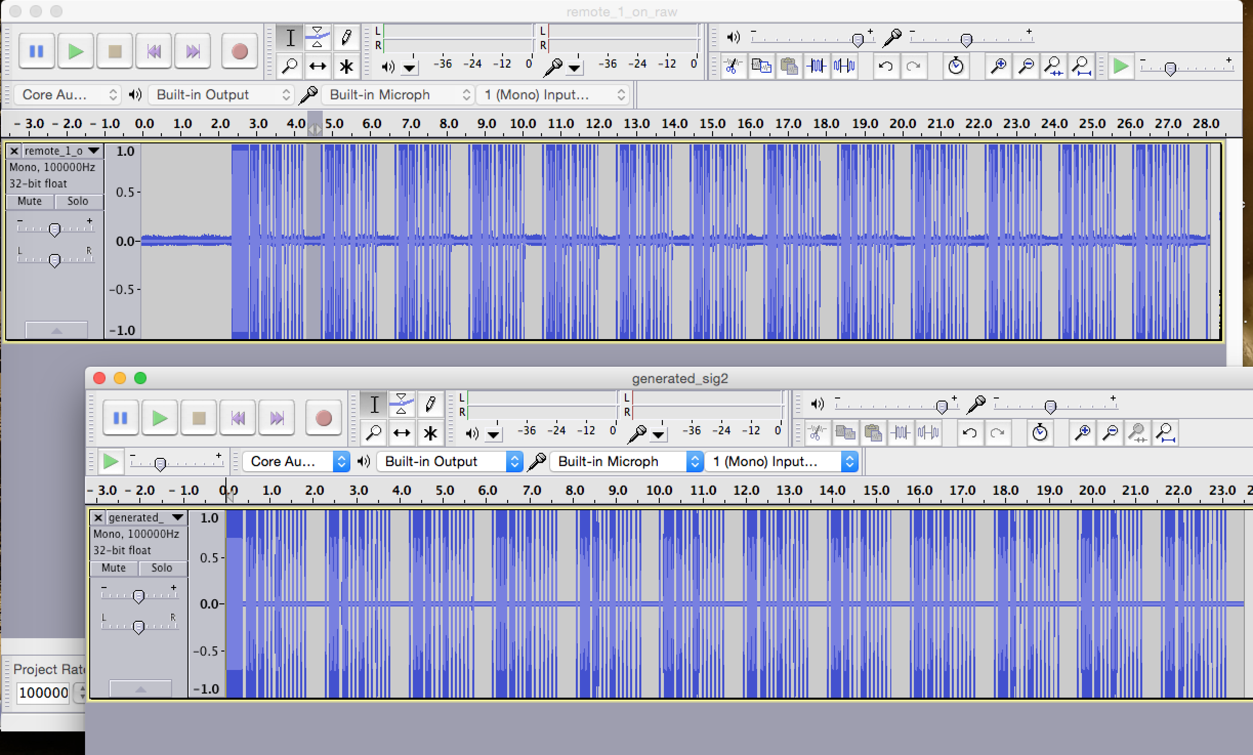
comparison
Complex number waves
It turns out that the HackRF only can transmit complex signals (essentially, a 2-dimensional sine wave, where time is the x axis, and the signal spins around the x axis in a helical shape that would appear like a sine wave when viewed perpendicularly).
So let's generate a complex signal...
There may be a better way, but the best way I know to generate a complex sine wave is with Euler's formula:
e^(i*t) = cos(t) + i sin(t)
Rotation with E animation
For more information on rotation with e, see https://github.com/calebmadrigal/FourierTalkOSCON/blob/master/05_RotationWithE.ipynb
t = np.linspace(0, 1, 1000)
amp = 3
freq = 10 # Hz
simple_sig = amp * np.cos(freq * 2 * np.pi * t)

plt.plot(t, simple_sig)

import cmath
complex_sig = 3 * np.e**(freq * 2 * np.pi * (0+1j) * t)
plt.plot(t, complex_sig)
simple_sig[5]
complex_sig[5]
abs(complex_sig[5]) # This is the amplitude of the wave
Now, let's rewrite the generation functions to use complex math
def generate_on_off_key_signal(binary_data, carrier_wave_freq, sample_rate,
                               baud, sig_ratios=DEFAULT_RATIOS, amp_map=DEFAULT_AMP_MAP, dtype=np.int16):
    signal_len_secs = len(binary_data) * (1/baud)
    t = np.linspace(0, signal_len_secs, sample_rate * signal_len_secs)

    # Using Euler's formula to generate a complex sinusoidal wave
    carrier_wave = 1 * np.e**(carrier_wave_freq * 2 * np.pi * (0+1j) * t)
    modulation_array = get_modulation_array(binary_data, sample_rate, baud, sig_ratios, amp_map, dtype)

    # Pad (or trim) the modulation array to match the length of the carrier wave
    if len(carrier_wave) > len(modulation_array):
        pad_len = len(carrier_wave) - len(modulation_array)
        modulation_array = np.append(modulation_array, np.full(pad_len, amp_map['LOW'], dtype=dtype))
    elif len(carrier_wave) < len(modulation_array):
        modulation_array = modulation_array[:len(carrier_wave)]

    return t, carrier_wave * modulation_array

def generate_pulse(bit_val, carrier_wave_freq, sample_rate, baud, multiple_of_bit_len,
                   amp_map=DEFAULT_AMP_MAP, dtype=np.int16):
    signal_len_secs = multiple_of_bit_len * (1/baud)
    t = np.linspace(0, signal_len_secs, sample_rate * signal_len_secs)

    high_or_low = 'HIGH' if bit_val == '1' else 'LOW'
    pulse = amp_map[high_or_low] * np.e**(carrier_wave_freq * 2 * np.pi * (0+1j) * t)
    return t, pulse
binary_data = '0110100010000000'
carrier_wave_freq = 315e6
sample_rate = 2e6
baud = 205

complex64_amp_map = {
    'LOW': 1.4 * .02,
    'HIGH': 1.4
}

t, complex_signal = generate_on_off_key_signal(binary_data, carrier_wave_freq, sample_rate, baud, amp_map=complex64_amp_map, dtype='complex64')
t2, signal_header = generate_pulse('1', carrier_wave_freq, sample_rate, baud, 3.85, amp_map=complex64_amp_map, dtype='complex64')
t3, signal_spacer = generate_pulse('0', carrier_wave_freq, sample_rate, baud, 3.78, amp_map=complex64_amp_map, dtype='complex64')

full_signal = join_all_arrays([signal_header] + ([complex_signal, signal_spacer] * 12))
write_pcm_file(full_signal, 'raw_data/generated_sig2.pcm', dtype='complex64')
Sadly, this signal did not trigger the outlet
So what's different? Well, for one, when I play the 2 signals audibly in Audacity, the original signal is pretty loud, whereas, the one I generated sounds really quiet - almost as if there is the waves I'm generating is self-canceling.
Here's a close-up of the wave I generated:
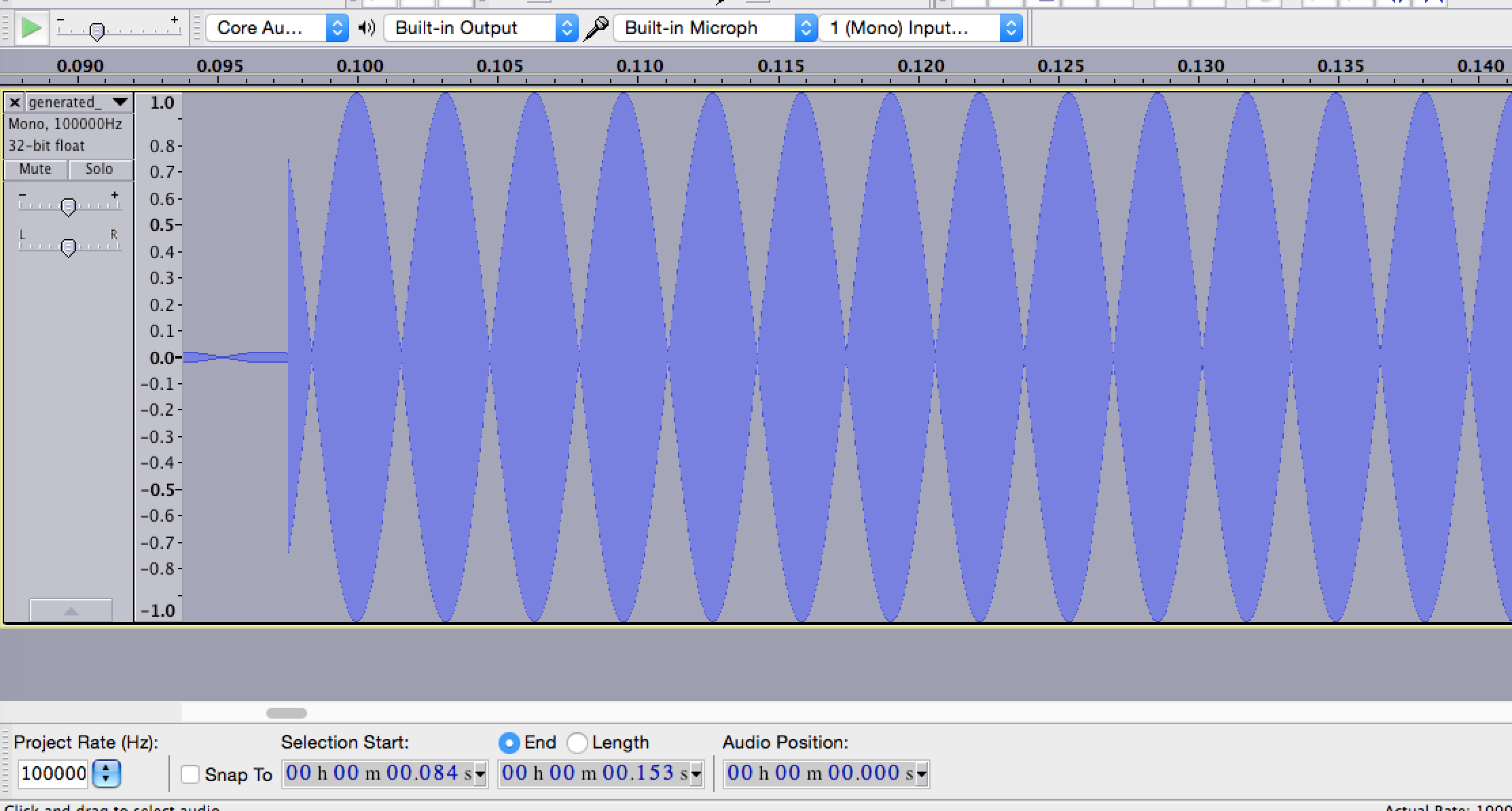
generated zoomed in
It almost looks like ther eare equal and opposite waves that would be canceling each other out, but when you look closer, it doesn't seem so:
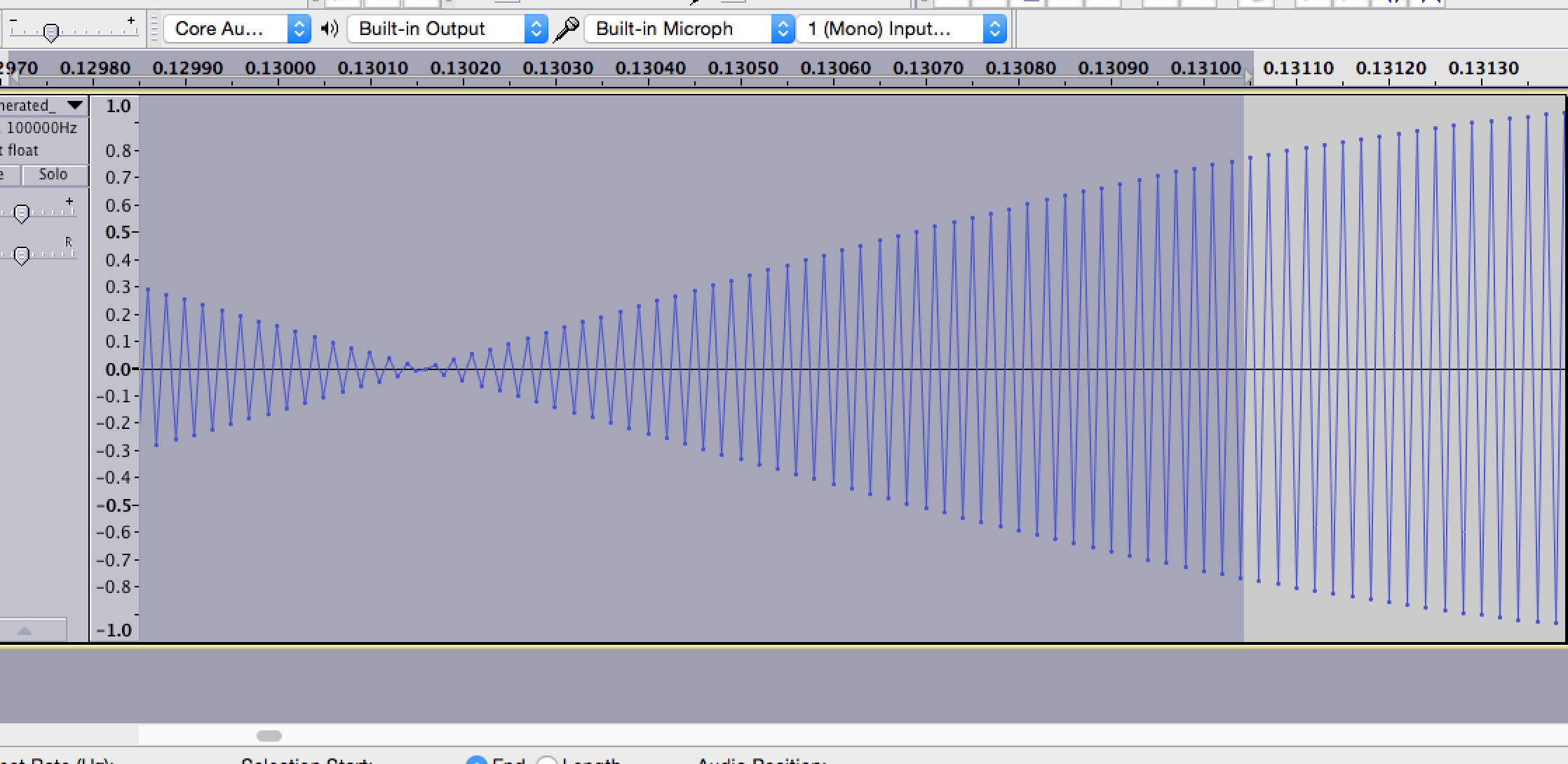
generated zoomed in
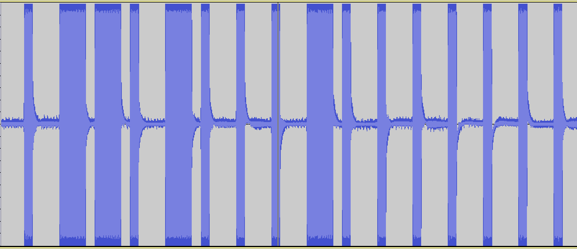
And here's a close-up of the original wave:
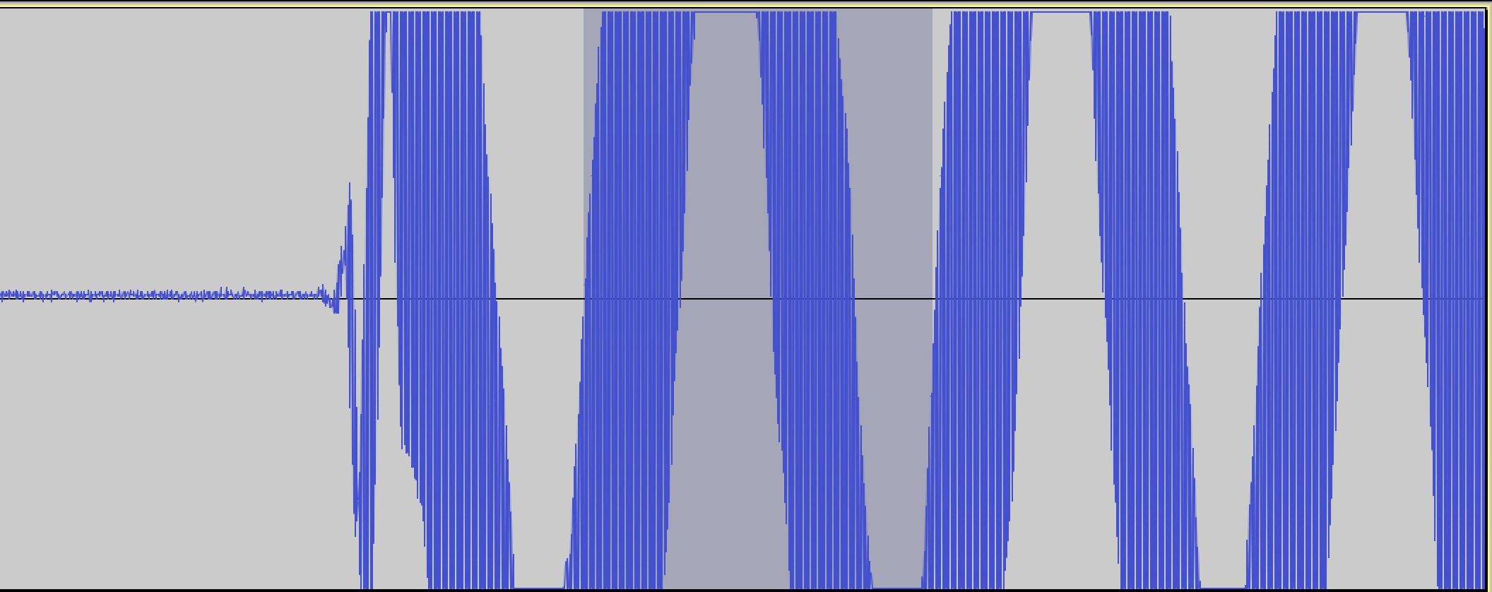
original zoomed in
It looks like in the original, the carrier wave is modulated by multiplying by another wave, rather than by unchanging "HIGH" values.
So I'm going to try that now: to modulate the carrier wave by another wave, rather than by a static HIGH value...
def generate_on_off_key_signal(binary_data, carrier_wave_freq, sample_rate,
                               baud, sig_ratios=DEFAULT_RATIOS, amp_map=DEFAULT_AMP_MAP, dtype=np.int16):
    signal_len_secs = len(binary_data) * (1/baud)
    t = np.linspace(0, signal_len_secs, sample_rate * signal_len_secs)

    # Using Euler's formula to generate a complex sinusoidal wave
    carrier_wave = 1 * np.e**(carrier_wave_freq * 2 * np.pi * (0+1j) * t)
    modulation_array = get_modulation_array(binary_data, sample_rate, baud, sig_ratios, amp_map, dtype)

    # Pad (or trim) the modulation array to match the length of the carrier wave
    if len(carrier_wave) > len(modulation_array):
        pad_len = len(carrier_wave) - len(modulation_array)
        modulation_array = np.append(modulation_array, np.full(pad_len, amp_map['LOW'], dtype=dtype))
    elif len(carrier_wave) < len(modulation_array):
        modulation_array = modulation_array[:len(carrier_wave)]

    # Modulate by superwave
    super_wave_freq = carrier_wave_freq / (160*2)
    super_wave = 1 * np.e**(super_wave_freq * 2 * np.pi * (0+1j) * t)

    return t, carrier_wave * modulation_array * super_wave

def generate_pulse(bit_val, carrier_wave_freq, sample_rate, baud, multiple_of_bit_len,
                   amp_map=DEFAULT_AMP_MAP, dtype=np.int16):
    signal_len_secs = multiple_of_bit_len * (1/baud)
    t = np.linspace(0, signal_len_secs, sample_rate * signal_len_secs)

    high_or_low = 'HIGH' if bit_val == '1' else 'LOW'
    pulse = amp_map[high_or_low] * np.e**(carrier_wave_freq * 2 * np.pi * (0+1j) * t)
    return t, pulse
binary_data = '0110100010000000'
carrier_wave_freq = 315e6
sample_rate = 2e6
baud = 205 * 2

complex64_amp_map = {
    'LOW': 1.4 * .02,
    'HIGH': 1.4
}

t, complex_signal = generate_on_off_key_signal(binary_data, carrier_wave_freq, sample_rate, baud, amp_map=complex64_amp_map, dtype='complex64')
t2, signal_header = generate_pulse('1', carrier_wave_freq, sample_rate, baud, 3.85, amp_map=complex64_amp_map, dtype='complex64')
t3, signal_spacer = generate_pulse('0', carrier_wave_freq, sample_rate, baud, 3.78, amp_map=complex64_amp_map, dtype='complex64')

full_signal = join_all_arrays([signal_header] + ([complex_signal, signal_spacer] * 12))
write_pcm_file(full_signal, 'raw_data/generated_sig3.pcm', dtype='complex64')
Success!
And this worked. I had to guess at the "super wave" frequency.
Here is what the generated signal looks like zoomed in:
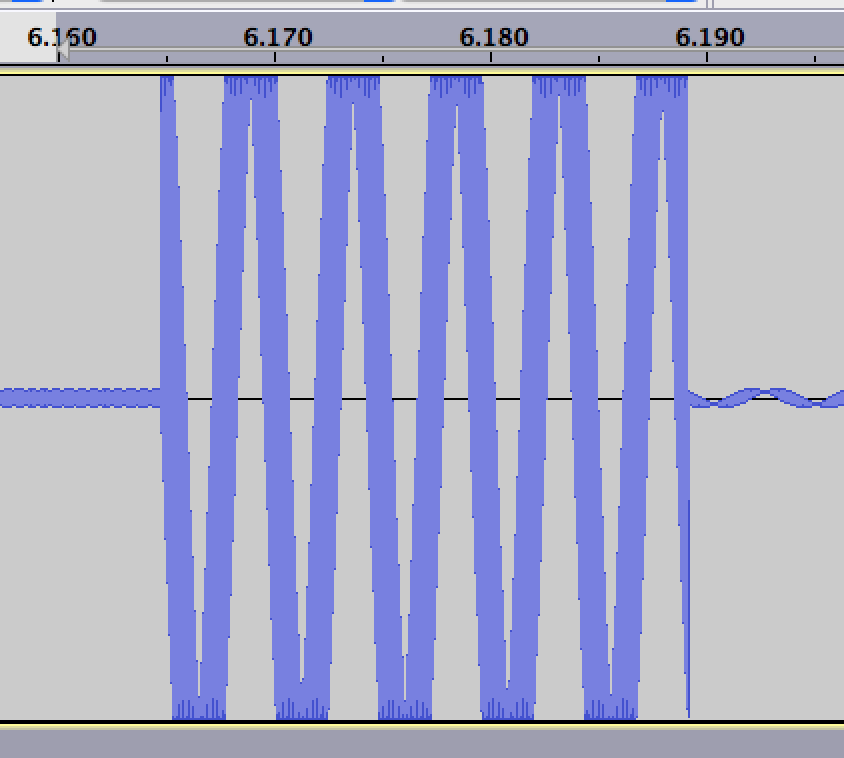
generated wave superwave
And here's the original signal:
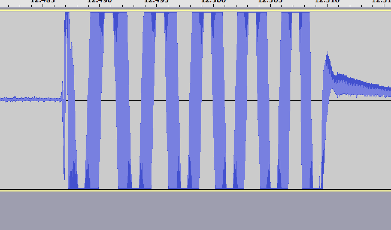
original wave superwave
So there you have it - how to generate a digital radio signal from scratch.